
From quick-turn prototypes to high-density multilayer production runs — engineered, sourced, and delivered through our network of ISO-certified and UL-registered manufacturing partners.
Our 370hr boards use high-glass-transition-temperature laminate engineered for lead-free assembly, repeated thermal cycling, and demanding industrial applications where standard FR4 falls short.
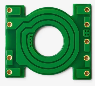
The 370hr designation refers to Isola's 370HR laminate — a high-performance FR4 variant engineered with a glass transition temperature (Tg) of ≥170°C, compared to ≈130°C for standard FR4. Its time-to-delamination (T-288) exceeds 30 minutes at 288°C, and it exhibits excellent resistance to conductive anodic filament (CAF) formation — a major cause of long-term insulation failure in high-humidity environments. These properties allow 370hr boards to survive lead-free solder reflow peaks (260°C+), repeated assembly cycles, and continuous operation at elevated temperatures without warping, measling, or delamination. Impedance-controlled multilayer builds on 370hr maintain tight dimensional stability across thermal excursions.
Design engineers specifying RoHS-compliant (lead-free) builds that must pass multiple reflow cycles without degradation. Engineers whose boards will operate continuously above 100°C — in telecom enclosures, near power electronics, or in automotive underhood environments. Tier-1 suppliers in industrial, telecom, and automotive who require certified material traceability and consistent laminate quality across production runs. Also the right choice for any multilayer build with strict impedance requirements, since higher-Tg laminates resist the dimensional shifts that throw controlled-impedance traces out of spec.
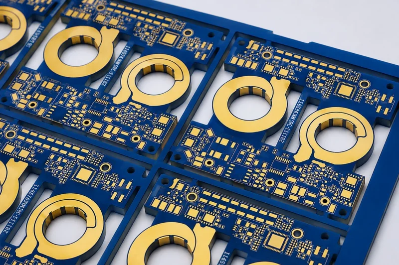
Standard and advanced rigid PCBs across a wide range of materials and complexity levels — produced with tight tolerances and consistent quality across every batch.
Rigid PCBs are the most versatile board type in electronics. J-Cube supplies single-layer through 20+ layer high-density interconnect (HDI) builds across a broad material range: standard FR4, high-Tg FR4 (370HR), Rogers high-frequency laminates (RO4003C, RO4350B, RO3003, RO3010), Teflon/PTFE, and polyimide for elevated-temperature use. Advanced builds feature buried and blind vias for tight signal routing, controlled impedance traces (±5–10% tolerance) for RF and high-speed digital signals, and fine-line traces down to 3mil/3mil for HDI designs. Multilayer counts up to 20+ layers are supported with sequential lamination for complex via structures. Rogers-material builds support frequencies from 1 GHz through 77 GHz for antenna, radar, and 5G applications.
Electrical engineers across virtually every industry — rigid PCBs are the default choice when the board won't flex and space or weight isn't critical. HDI builds serve compact consumer and industrial devices where component density is high. Rogers and PTFE-based builds are for RF, microwave, and millimeter-wave system designers who need controlled dielectric constant and low loss tangent. High-layer-count builds serve complex digital systems in networking, server, and instrumentation applications. Standard FR4 builds cover the widest range of cost-sensitive industrial and commercial applications.
Aluminum and copper metal-core PCBs designed to dissipate heat in LED lighting, automotive, and high-power applications — extending component life and improving reliability.
A metal-core PCB (MCPCB) replaces the FR4 substrate with a metal base — most commonly aluminum (1.0–3.2mm thick) or copper — bonded to the circuit layer via a thin thermally conductive dielectric (typically 0.075mm–0.15mm). This stack conducts heat from LEDs or power components directly into the metal base at 1–3 W/m·K for aluminum-core boards, or up to 380 W/m·K for copper-core boards — compared to just 0.3 W/m·K for standard FR4. Lower LED junction temperatures translate directly to longer lifespan (every 10°C reduction roughly doubles LED life) and maintained lumen output over time. J-Cube supplies single-sided and double-sided MCPCB in aluminum and copper cores, with dielectric thermal conductivity values selectable based on the application's heat load.
LED lighting OEMs who need to maintain junction temperatures below 85°C without bulky external heatsink assemblies. Automotive lighting designers specifying headlamp and DRL modules where the board itself must contribute to thermal management. Power electronics engineers designing compact modules — motor drives, on-board chargers, solar micro-inverters — where a passive PCB-integrated thermal path reduces BOM and assembly cost versus a separate heatsink. Also suited to any application where FR4's thermal resistance is creating reliability or lifetime problems.
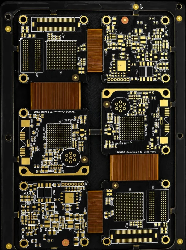
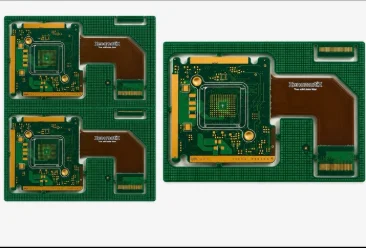
Rigid-flex PCBs combine rigid FR4 sections with flexible polyimide (Kapton) layers, allowing the board to fold, twist, or wrap around components. Ideal for aerospace, medical devices, wearables, automotive electronics, and any product where space, weight, or reliability under repeated motion are constraints.
Rigid-flex PCBs are fabricated as a single laminated structure — FR4 rigid zones for component mounting and structural support, with polyimide (Kapton) flex zones bonded between and around them. Unlike a separate flex cable and PCB, the rigid-flex is one continuous circuit: no connectors, no solder joints at the interface, no mechanical wear at the junction. Flex zones are designed either for static flex (bent once during assembly into final position) or dynamic flex (rated for millions of repeated flexure cycles in service). Key design considerations include minimum bend radius (typically 10× the flex thickness), copper hatching in bend zones for strain relief, and coverlay (not soldermask) in the flex regions. Rigid-flex increases design complexity and unit cost versus rigid-only boards but dramatically reduces overall system assembly cost, mass, and failure risk.
Product engineers at aerospace, defense, medical device, wearable, robotics, and premium consumer electronics OEMs where interconnect reliability is non-negotiable, or where reducing form factor and mass is a hard requirement. Systems that would otherwise require multiple PCBs connected by ribbon cables or micro-connectors are ideal candidates — eliminating those connectors removes the most common failure point in complex assemblies. Also increasingly used in compact industrial electronics, camera modules, and automotive electronics where multiple PCBs need to fit into irregular enclosures.
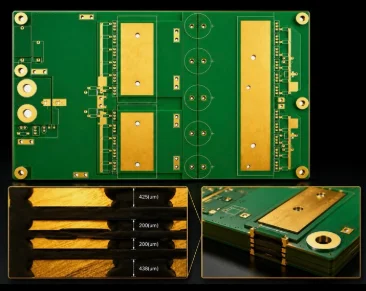
Thick-copper PCBs (typically 2oz to 20oz) built to carry heavy current, withstand thermal stress, and deliver exceptional durability in industrial, automotive, and power-distribution applications.
Heavy copper PCBs use copper weights from 2oz to 20oz per square foot on inner and/or outer layers — standard production PCBs use 1oz copper. As a reference point, a 4oz copper, 10mm-wide trace can carry over 50A continuously while staying within safe temperature limits. Heavier copper also significantly improves thermal performance (copper conducts heat at ~385 W/m·K) and mechanical durability, reducing susceptibility to thermal cycling-induced trace cracking. J-Cube supports mixed-weight designs where signal layers use standard 1oz copper and power planes use 4oz, 6oz, or heavier copper, optimizing cost and performance. Achieving heavy copper weights while maintaining tight trace definition requires specialized etching chemistry and process control — J-Cube's manufacturing partners have established experience fabricating up to 20oz boards with controlled trace profiles.
Power electronics engineers who need to carry tens or hundreds of amperes on-board without resorting to external bus bars. EV and hybrid vehicle system designers managing high-current paths in battery management, charging, and drivetrain modules. Industrial automation OEMs specifying motor controller and servo drive boards. Data center infrastructure engineers designing power distribution at the board level. Renewable energy equipment manufacturers building inverters, charge controllers, and combiner boxes where thermal management is a primary design constraint.
High-power PCBs purpose-built for power conversion, motor control, EV/inverter systems, and industrial drives — combining thick copper, robust dielectrics, and optimized thermal pathways to handle demanding voltage and current loads.
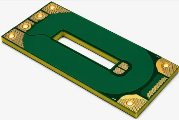
High-power PCBs are purpose-engineered for systems operating at high voltage (>600V DC or AC), high current, or high switching frequencies where standard PCB design rules are insufficient. Design rules address creepage and clearance distances per IEC 60950 and IPC-2221 for operating voltages from 600V through 10kV+, partial-discharge-resistant dielectric selection, and copper pour and thermal via optimization for low thermal resistance to heatsinks or cold plates. Materials include standard FR4, high-Tg FR4, Rogers laminates, and ceramic-filled PTFE for the most demanding high-frequency power switching applications. J-Cube's manufacturing partners have experience with designs relevant to IEC 60950, IPC-9592, and UL 62368-1 standards, including SiC and GaN gate driver board requirements.
Power electronics engineers designing grid-connected or high-voltage isolated systems. EV drivetrain and charging teams working with 400V–800V battery architectures. Grid inverter OEMs whose designs must meet utility interconnect standards. Industrial drives manufacturers specifying VFDs, servo amplifiers, and soft starters. Railway traction electronics suppliers with IEC 61373 and EN 50155 compliance requirements. Also relevant for telecom rectifier and DC-DC converter designers managing 48V bus or higher-voltage distribution.
A summary of materials, processes, and specifications available across our product lines.
Capability sheets for our core PCB product lines, available in English and French.
Complete company overview: capabilities, materials, technologies, industries served, and manufacturing process.
Engineered for extreme power density: heavy copper up to 17oz, high current, and demanding thermal loads.
Polyimide-based flexible and rigid-flex constructions for compact, high-reliability designs — up to 30+ layers.